
Here is the new circuit diagram.

And the finished circuit:
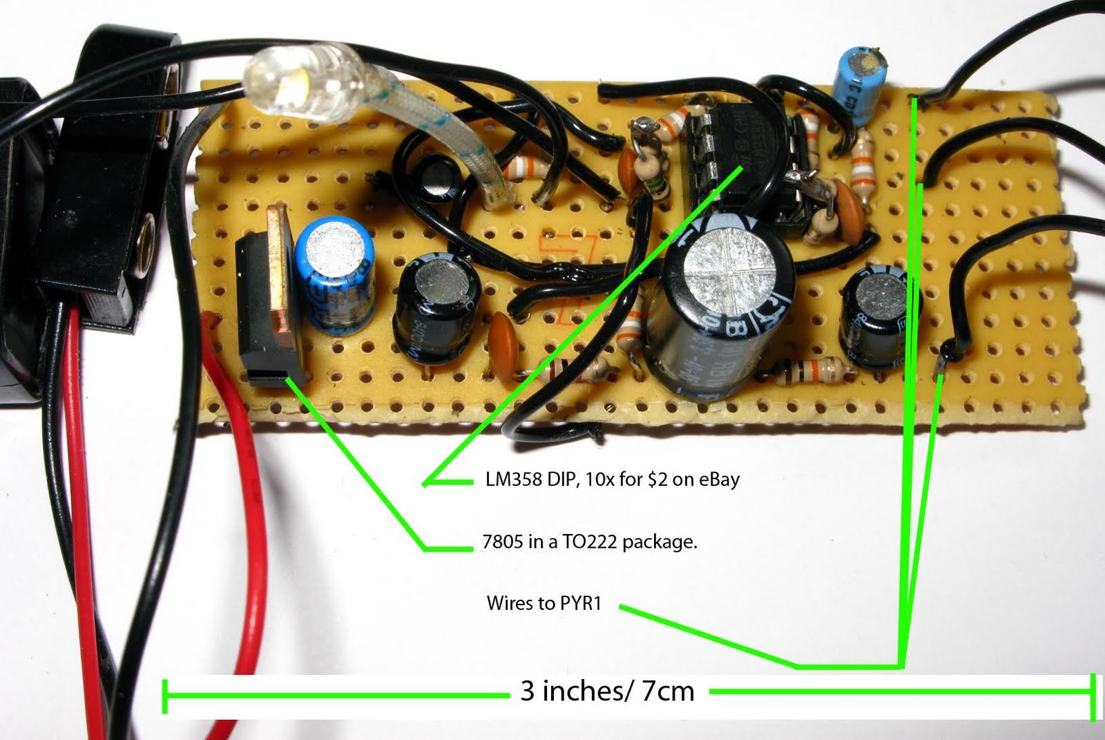
By doing away with the comparator and 555 timer the board comes in at 3" by 1". These have been replaced with a variable resistor (which is a little big here, but was chosen cos it has an inbuilt switch) and super bright LED. The LED switches on and off quite sharply at the right voltage, and can be controlled with the variable resistor.
The completed device below measures 9" but this can easily be reduced to 6 or 7 with a bit of trimming and a smaller trimmer.

Here you can see the Pot, Battery, circuit and to the top the PIR sensor it's self.
Tested it out last night and without a lens range is about 8 meters, a lens is therefore vital to increasing range to a more useable level.
Heres the strip board layout, which should also help you cut down planning time.


How did you test your device?
ReplyDelete